A line follower is just like a hello world in robotics. Many have been made and nowadays are based on arduino boards, this time I want to go old school and build this simple line follower from parts on my bin. The DS89C430 is a fast 8051 core variant from Maxim, before the era of arduino these are the microcontrollers that only requires UART connection and do not require a external programmer to load the bootloader because it is loaded with bootloader already from the factory and only a terminal program is required to load the hex file generated from the assembler or compiler.
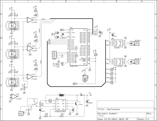
This line follower consist of 3 TCRT5000 reflective IR sensors that goest to a LM339 quad comparator that gives the microcontroller a high or low signal when a black line is detected or not. A L9110S motor driver module was used to drive the two DC motors in differential drive mode. The whole project is powered by a single 3.7V 18650 battery from an old laptop battery pack. The output is fed to a boost converter based on the classic MC34063 to boost the battery voltage to 5V. The complete schematic is show below.
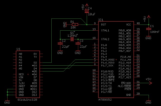
Schematic Diagram
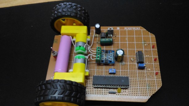
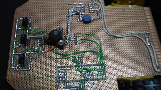
The whole project is built on a strip board with mixed thru hole and surface mount components depending on what I have on my bin.
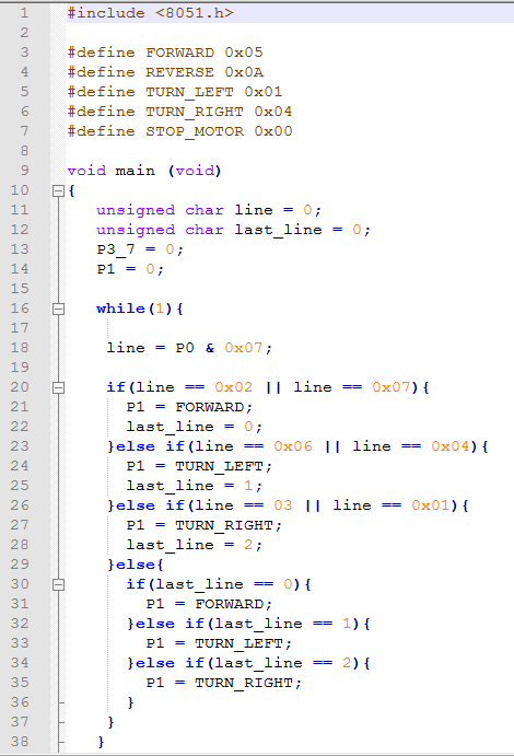
And now the code! Basically a logic based on its position on the track. One motor is stopped to make a turn. The code is compiled with SDCC.
Voila! a nice line follower that can navigate even a complicated track! See the video demo below
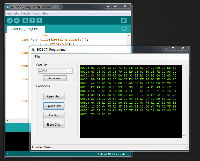
This project was lost, luckily while digging I found a backup file. I am now making this project available for public use. Released as is with no warranties, I am not liable for any harm done to your system. This should be used ONLY FOR EDUCATIONAL PURPOSES. The client file requires .NET Framework 4.0. The arduino sketch was compiled and tested with Arduino IDE 1.0.5 and Gizduino 328 (Arduino clone in the Philippines by e-Gizmo Mechatronics Central). The program for the 8051 was compiled with SDCC.
Connection Diagram:
Instructions:
1. Select the Correct COM Port
2. Connect
3. Load up the Hex file
4. Upload Hex file to your MCU
5. Grab a beer and enjoy!
This is my first post for the year, been busy for a while. The Pbot is an entry level mobile robot learning platform locally available in e-gizmo here in the Philippines. It contains three channel IR collision sensor, 3 Channel line sensor and a dual motor driver. Any arduino compatible platform can be used as the controller. It is a fun mobot platform to play with, can be configured as a line follower, a mazer or a sumobot or even a soccer bot.
A quick weekend project to play with this mobot platform is to control it with VB.net thru Bluetooth Serial Port. When playing with these toys, it is important to know whether your battery still have the juice so you can enjoy playing, but the old board (that I have) don’t have a connection for battery feedback. My quick solution is to put a voltage divider (two 100K resistors) between the battery terminals and feed it to the Analog Input 0 of the controller.
The Arduino program transmits data every second to the computer then waits for a character from the Computer, When a correct character is received, then it tells the motors what to do.
Voila! Vb.net Controlled Pbot with Battery Status Feedback
The code listing for the Arduino
/*

'Pbot Remote Control with VB.net 2010

'Copyright (C) 2014  Richard Myrick T. Arellaga

'

'This program is free software: you can redistribute it and/or modify

'it under the terms of the GNU General Public License as published by

'the Free Software Foundation, either version 3 of the License, or

'(at your option) any later version.

'

'This program is distributed in the hope that it will be useful,

'but WITHOUT ANY WARRANTY; without even the implied warranty of

'MERCHANTABILITY or FITNESS FOR A PARTICULAR PURPOSE.  See the

'GNU General Public License for more details.

'

' You should have received a copy of the GNU General Public License

' along with this program.  If not, see .

*/
int batt = 0;
float voltage = 0;
long prevMillis = 0;
long interval = 1000;
int rx = 0;
const int M1DIR = 8;
const int M1RUN = 9;
const int M2RUN = 10;
const int M2DIR = 11;
//read actual VCC of arduino for a more accurate adc reading
long readVcc() {
long result;
// Read 1.1V reference against AVcc
ADMUX = _BV(REFS0) | _BV(MUX3) | _BV(MUX2) | _BV(MUX1);
delay(2); // Wait for Vref to settle
ADCSRA |= _BV(ADSC); // Convert
while (bit_is_set(ADCSRA,ADSC));
result = ADCL;
result |= ADCH<<8;
result = 1126400L / result; // Back-calculate AVcc in mV
return result/1000;
}
VB.net Code Listing
'Pbot Remote Control with VB.net 2010

'Copyright (C) 2014  Richard Myrick T. Arellaga

'

'This program is free software: you can redistribute it and/or modify

'it under the terms of the GNU General Public License as published by

'the Free Software Foundation, either version 3 of the License, or

'(at your option) any later version.

'

'This program is distributed in the hope that it will be useful,

'but WITHOUT ANY WARRANTY; without even the implied warranty of

'MERCHANTABILITY or FITNESS FOR A PARTICULAR PURPOSE.  See the

'GNU General Public License for more details.

'

' You should have received a copy of the GNU General Public License

' along with this program.  If not, see .
Imports System.IO.Ports
Imports System.Text
Public Class Form1
Private pendingMsg As New StringBuilder()
Private Sub GetCOMPortList()
Dim i As Integer
Dim foundDifference = False
If cboCOMPorts.Items.Count = SerialPort.GetPortNames().Length Then
For Each s As String In SerialPort.GetPortNames()
If cboCOMPorts.Items(System.Math.Max(System.Threading.Interlocked.Increment(i), i - 1)).Equals(s) = False Then
foundDifference = True
End If
Next
Else
foundDifference = True
End If
If foundDifference = False Then
Return
End If
cboCOMPorts.Items.Clear()
For Each s As String In SerialPort.GetPortNames()
cboCOMPorts.Items.Add(s)
Next
cboCOMPorts.SelectedIndex = 0
End Sub
Private Sub serialPort1_DataReceived(ByVal sender As Object, ByVal e As SerialDataReceivedEventArgs) Handles SerialPort1.DataReceived
Dim completeMsg As String
completeMsg = String.Empty
pendingMsg.Append(SerialPort1.ReadExisting())
If pendingMsg.Length >= 6 Then
completeMsg = pendingMsg.ToString(0, 6)
pendingMsg.Remove(0, 6)
Me.Invoke(New Action(
Sub()
txtRxData.Text = completeMsg
End Sub))
End If
End Sub
Private Sub Form1_Load(ByVal sender As System.Object, ByVal e As System.EventArgs) Handles MyBase.Load
btnDisconnect.Enabled = False
GetCOMPortList()
End Sub
Private Sub btnConnect_Click(ByVal sender As System.Object, ByVal e As System.EventArgs) Handles btnConnect.Click
Try
SerialPort1.PortName = cboCOMPorts.Items(cboCOMPorts.SelectedIndex).ToString()
SerialPort1.BaudRate = 9600
SerialPort1.ReadTimeout = 1000
SerialPort1.Open()
btnDisconnect.Enabled = True
btnConnect.Enabled = False
Catch ex As Exception
btnDisconnect.PerformClick()
End Try
End Sub
Private Sub btnDisconnect_Click(ByVal sender As System.Object, ByVal e As System.EventArgs) Handles btnDisconnect.Click
Try
SerialPort1.DiscardInBuffer()
SerialPort1.DiscardOutBuffer()
SerialPort1.Close()
btnConnect.Enabled = True
btnDisconnect.Enabled = False
Catch ex As Exception
End Try
End Sub
Private Sub btnFW_Click(ByVal sender As System.Object, ByVal e As System.EventArgs) Handles btnFW.Click
If (SerialPort1.IsOpen()) Then
SerialPort1.Write("W")
End If
End Sub
Private Sub btnBack_Click(ByVal sender As System.Object, ByVal e As System.EventArgs) Handles btnBack.Click
If (SerialPort1.IsOpen()) Then
SerialPort1.Write("S")
End If
End Sub
Private Sub btnLeft_Click(ByVal sender As System.Object, ByVal e As System.EventArgs) Handles btnLeft.Click
If (SerialPort1.IsOpen()) Then
SerialPort1.Write("A")
End If
End Sub
Private Sub btnRight_Click(ByVal sender As System.Object, ByVal e As System.EventArgs) Handles btnRight.Click
If (SerialPort1.IsOpen()) Then
SerialPort1.Write("D")
End If
End Sub
Private Sub btnStop_Click(ByVal sender As System.Object, ByVal e As System.EventArgs) Handles btnStop.Click
If (SerialPort1.IsOpen()) Then
SerialPort1.Write("Q")
The Microchip Pickit2 is one of the most hobby friendly PIC programmer in the market. It lets you program the chip within MPLAB and the most important feature is its USB connectivity. I used a JDM based programmer which confines me of programming with my desktop until I had my PIKIT2, electronicslab.ph version of the original pickit2. At work I am using a PICSTART plus programmer which annoys me because I cannot do on the fly update on the development board because I always have to remove the IC from the board then put it in the programmer back to the board so I made this quick simplified pickit2 from the parts I have.
Prototype
The original pickit2 requires a 680uH inductor and a 20Mhz clock, but I only have a 220uH inductor and a 12Mhz crystal so i gave it a try. I programmed the PIC18F2550 with the PICSTART within MPLAB, to use the 12Mhz crystal the PLL prescaler selection bit must be modified to divide by 3. This version of the pickit2 is a strip down version intended for hobbyist and students that do not require the progammer to go feautres, also DO NOT use this pickit2 version on 3.3V PICs since the part for adjusting target VDD is also taken out.
I tested it with another PIC18F2550 and voila! this programmer works like a charm even with a 12Mhz crystal and a 220uH inductor on the VPP circuit. This programmer was also tested with PIC16F628A, PIC12F609 and PIC10F202 without problems.
Schematic
The firmware of the PIC used in the programmer can be found on Program Files\Microchip\MPLAB IDE\PICKit2\PK2V023200.hex. The JDM programmer can also be used to program the PIC18F2550 for the first time, just dont forget to change the PLLDIV to divide by 3 when using a 12Mhz crystal, but when a 20Mhz crystal is used no need to changed anything on the PICkit2 firmware.
The serial port on our computers are with us for quite sometime now. It is more favored than the parallel port for interfacing with the outside world because it require lesser wires and can go farther distance and can even be used with newer technologies such as Bluetooth using its serial port capability. In this tutorial is a quick start guide in communicating with the serial port using VB.net without any previous knowledge.
Before we start, VB.net 2010 must be installed. The installer can be freely downloaded from Microsoft.
Start Visual Basic 2010 Express and you will be prompted with the Start Page Window
Select on New Project and select Windows Form Application and give the Project a name, in this case I named it Serial Port Interface.
A blank form will be displayed named Form1. This is the main form which will contain all other controls.
Click on the toolbox to show the controls, you may want to click on the pin to disable the autohide feature
Click on the form and change its name to frmMain (for easier identification specially when adding more forms). Also, change its name, in this case VB.net Terminal – Philrobotics. This name will be the one that will be displayed on the title bar. Since this program is only a small program, we can disable the Maximize button by setting MaximizeBox value on the form’s property to false.
Let’s start to add some controls to our form. From the common Controls, add (2) two labels, (2) two combo box and (2) two buttons. Change the text of the first label to “Com Port:” and the second one to “Baud Rate:”. For the combo box change its name to cmbPort and cmbBaud for the purposes of easier identification when we will add the codes to our controls. Also, change the text of the two buttons, the first to “Connect” and the second to “Disconnect” and change their name to btnConnect and btnDisconnect. As you can see, I use cmb and btn prefix to refer to combo box and button same reason as above, for easier identification.
Next, from the Containers add two Group box and change its text to “Transmit Data” and “Received Data”. Inside the Transmit Data group box, add a textbox and a button. Change the name of the textbox to txtTransmit and the button to btnSend, also change its text to Send. On the Received Data group box, add a Rich Text Box and change its name to rtbReceived. Lastly and the most important, add the SerialPort from the components.
Now, we come to the next part, adding the instructions to our program. To start coding double click the form or press F7 to view the code. To add a code to individual controls just go back to the designer view or press Shift+F7 and double click a control to add code into it.
For instance if we double click on the Send button on the designer view the Code Editor will take us to
Private Sub btnSend_Click(ByVal sender As System.Object, ByVal e As System.EventArgs) Handles btnSend.Click
On this Part is where we enter our codes.
End Sub
To complete our program put the following codes to the code editor:
‘Serial Port Interfacing with VB.net 2010 Express Edition
‘Copyright (C) 2010 Richard Myrick T. Arellaga
‘
‘This program is free software: you can redistribute it and/or modify
‘it under the terms of the GNU General Public License as published by
‘the Free Software Foundation, either version 3 of the License, or
‘(at your option) any later version.
‘
‘This program is distributed in the hope that it will be useful,
‘but WITHOUT ANY WARRANTY; without even the implied warranty of
‘MERCHANTABILITY or FITNESS FOR A PARTICULAR PURPOSE. See the
‘GNU General Public License for more details.
‘
‘ You should have received a copy of the GNU General Public License
‘ along with this program. If not, see <http://www.gnu.org/licenses/>.
Imports System
Imports System.ComponentModel
Imports System.Threading
Imports System.IO.Ports
Public Class frmMain
Dim myPort As Array ‘COM Ports detected on the system will be stored here
Delegate Sub SetTextCallback(ByVal [text] As String) ‘Added to prevent threading errors during receiveing of data
Private Sub frmMain_Load(ByVal sender As System.Object, ByVal e As System.EventArgs) Handles MyBase.Load
‘When our form loads, auto detect all serial ports in the system and populate the cmbPort Combo box.
myPort = IO.Ports.SerialPort.GetPortNames() ‘Get all com ports available
cmbBaud.Items.Add(9600) ‘Populate the cmbBaud Combo box to common baud rates used
cmbBaud.Items.Add(19200)
cmbBaud.Items.Add(38400)
cmbBaud.Items.Add(57600)
cmbBaud.Items.Add(115200)
For i = 0 To UBound(myPort)
cmbPort.Items.Add(myPort(i))
Next
cmbPort.Text = cmbPort.Items.Item(0) ‘Set cmbPort text to the first COM port detected
cmbBaud.Text = cmbBaud.Items.Item(0) ‘Set cmbBaud text to the first Baud rate on the list
btnDisconnect.Enabled = False ‘Initially Disconnect Button is Disabled
End Sub
Private Sub btnConnect_Click(ByVal sender As System.Object, ByVal e As System.EventArgs) Handles btnConnect.Click
SerialPort1.PortName = cmbPort.Text ‘Set SerialPort1 to the selected COM port at startup
SerialPort1.BaudRate = cmbBaud.Text ‘Set Baud rate to the selected value on
‘Other Serial Port Property
SerialPort1.Parity = IO.Ports.Parity.None
SerialPort1.StopBits = IO.Ports.StopBits.One
SerialPort1.DataBits = 8 ‘Open our serial port
SerialPort1.Open()
Private Sub btnDisconnect_Click(ByVal sender As System.Object, ByVal e As System.EventArgs) Handles btnDisconnect.Click
SerialPort1.Close() ‘Close our Serial Port
btnConnect.Enabled = True
btnDisconnect.Enabled = False
End Sub
Private Sub btnSend_Click(ByVal sender As System.Object, ByVal e As System.EventArgs) Handles btnSend.Click
SerialPort1.Write(txtTransmit.Text & vbCr) ‘The text contained in the txtText will be sent to the serial port as ascii
‘plus the carriage return (Enter Key) the carriage return can be ommitted if the other end does not need it
End Sub
Private Sub SerialPort1_DataReceived(ByVal sender As Object, ByVal e As System.IO.Ports.SerialDataReceivedEventArgs) Handles SerialPort1.DataReceived
ReceivedText(SerialPort1.ReadExisting()) ‘Automatically called every time a data is received at the serialPort
End Sub
Private Sub ReceivedText(ByVal [text] As String)
‘compares the ID of the creating Thread to the ID of the calling Thread
If Me.rtbReceived.InvokeRequired Then
Dim x As New SetTextCallback(AddressOf ReceivedText)
Me.Invoke(x, New Object() {(text)})
Else
Me.rtbReceived.Text &= [text]
End If
End Sub
Private Sub cmbPort_SelectedIndexChanged(ByVal sender As System.Object, ByVal e As System.EventArgs) Handles cmbPort.SelectedIndexChanged
If SerialPort1.IsOpen = False Then
SerialPort1.PortName = cmbPort.Text ‘pop a message box to user if he is changing ports
Else ‘without disconnecting first.
MsgBox(”Valid only if port is Closed”, vbCritical)
End If
End Sub
Private Sub cmbBaud_SelectedIndexChanged(ByVal sender As System.Object, ByVal e As System.EventArgs) Handles cmbBaud.SelectedIndexChanged
If SerialPort1.IsOpen = False Then
SerialPort1.BaudRate = cmbBaud.Text ‘pop a message box to user if he is changing baud rate
Else ‘without disconnecting first.
MsgBox(”Valid only if port is Closed”, vbCritical)
End If
End Sub
End Class
After putting all the codes we are now ready to compile our project. To do this go to, Debug -> Build SerialPortInterface. If there are no errors, It will indicate Build Succeeded at the status bar.
The executable file of the compiled project is usually located at the bin\Release of the project folder.
To test if our program is working, short the TX and RX pin of your serial port and press F5 or click on the green triangle. Each data that we send must also be received by our program. In my setup I’m using a USB-to-Serial Converter and is allocated at COM18.
Getting started with mobile robots, we definitely need a platform where we can fit the electronics of our robot and make it move. In this tutorial we will be making a cheap mobile robot platform from a toy commonly called as tumbling car here in the Philippines. It can be bought almost anywhere specially on Chinese discount stores at 40-50 pesos.
The Materials:
2 – Tumbling car
1 – Small screwdriver
1 – Side Cutter or small saw
1 – Super glue
Let’s get started:
First, unscrew the top cover by removing the two screws at the bottom side of the toy
Toys with top cover removed
Next, remove the wheels opposite the motor and the gearbox as shown
Trim down the shaft for proper alignment
Put super glue all around on one of the cars
Align and put them together
You may add a plastic or metal link for more strength and ruggedness against bumps like the one shown below
Wait for the superglue to dry and voila!, you now have a less than 200 Pesos robot platform in less than 30 minutes
When doing a project that needs a 1Hz clock source, we usually use LM555 configured as astable mode as a clock source. The circuit above is an alternative 1Hz source. Since we are using 60Hz in the Philippines, the circuit is designed to divide the frequency to 1Hz.
The input is connected to the secondary of the transformer of the power supply section of the project. The zener diode clamps the voltage to 5V since we are using TTL glue logic. The CD4022 divides the clock input of 60Hz to 10Hz, its output is then connected to a decade counter which further divides the 10Hz to 1Hz thus providing a clock source to your glue logic digital clock project or anything that needs a 1Hz source. The circuit can be used with countries using 50Hz by changing the connection to CD4022’s Q6 transferred to Q5. Credit to Redskin of elab
If you need a large seven segment for your prototypes and can’t afford the high cost of commercial large seven segment, you can build your own using LED’s and some art supplies.
Raw Materials
I made use of a styropor as a mold for the segment displays and also as a holder for the LED’s. Each segment contains a single LED (sorry I forgot to take a picture). The Felt paper serves as the cover and tracing paper was used as light diffusers.
Messy Back Wiring
The hardest part of the project is wiring! Wire each common of the LED’s for this project a common cathode and connect all A to G segments.
Testing segments if all are working. The demo is a little bit dim because i’m running it at 5V with a current limiting resistor only no drivers yet.
Here is another set of tutorial made by one of Electronicslab.ph finest, Paranz. This is for the Zilog Z8 Encore Family of Microcontrollers unlike the previous Zilog chip, Encore are flash based which means that they are re programmable and one can make his own demo board.
The Z86E04 is a family of OTP microcontroller from Zilog. This chip is widely used in universities to teach students the basics of microcontroller programming. This tutorial containts 11 lessons from lighting LEDs , using seven segments, driving motors to using the internal comparator as ADC.