Brushed Direct Current Motors or commonly referred to as DC motor is the most common among the motors we use in every day life. A brushed DC motor can be small like those that are used in toy cars, others are more larger and powerful like those that are used in cordless electric drills. These motors can be directly connected to a battery then they spin, if we reverse the connection of the battery, the direction of rotation changes.

Different DC Motors
These motors usually operates at a higher voltage and requires much larger current. To interface it to the microcontroller, we use a driver to handle the larger voltage and current required by the motor. For simple operations like if you only want to turn the motor on and off, or need to control its speed, a simple transistor is used. However, if you would like to reverse the direction of rotation, we will be using a circuit called H-Bridge.

Shown above is one of the common way of connecting the motor, using a transistor. The transistor must be chosen that it can handle the current of the motor even if it is in stalled condition. Small DC motors found in toys can go as high as 1.5A. The motors produce reverse EMF that can destroy our transistor as well as the microcontroller, the addition of the diode protects us from these large amount of reverse voltage produced. The transistor is operated in cut-off and saturation regions, thus it acts as a switch, the resistor R1 limits the current going to the base of the transistor.
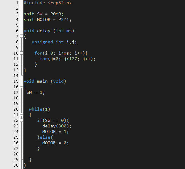
The above code will turn on the motor if a switch connected at P0 is pressed, then it will turn off the motor if not pressed. Basically, just like turning an LED on and off.
Now, if we want to reverse the direction, we need to connect our motor to an h-bridge circuit.

A h-bridge is just like 4 switches lined up and the motor at the center forming an H shape. If S1 and S4 are closed the current will flow at a certain direction, if S2 and S3 are closed the direction of current flow reverses, resulting to a change in the direction of rotation. H-bridge can be build by BJT Transistor or MOSFET. It only needs 2 pins from the microcontroller to control the direction and to stop the motors.

Nowadays, integrated h-bridge drivers such as L298 and L293D can be easily obtained. The L298 can handle upto 1.5A while the L293D can handle at most 600mA

If working with larger motors, it is wise to use a beefier H-bridge such as the Beefy H-Bridge Motor driver which can handle upto 6A motor load or a BTS7960 based if you need current up to 43A.

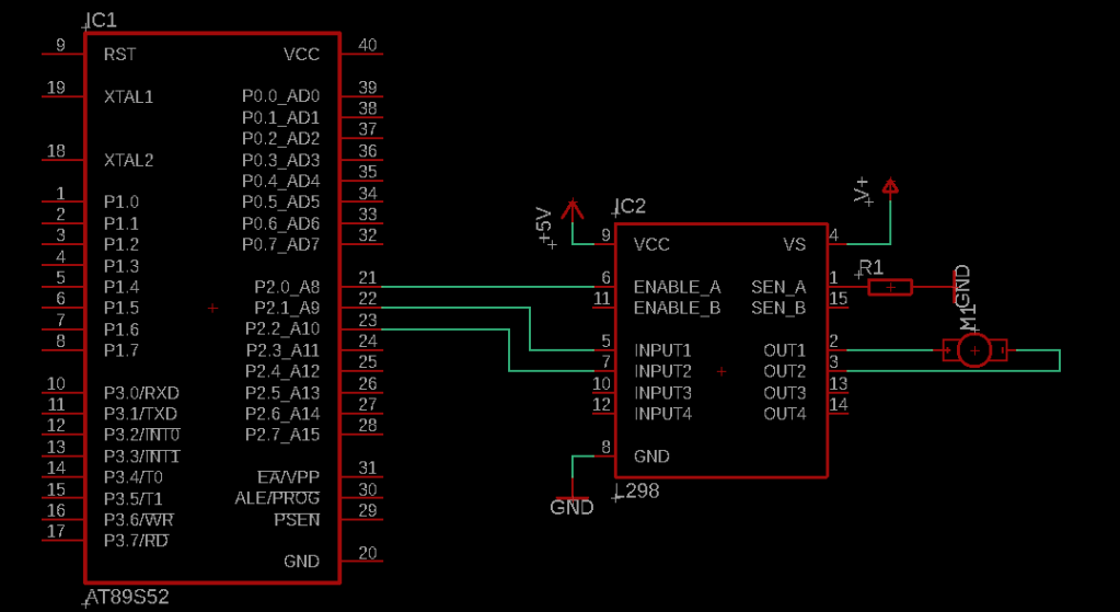
Considering a L298 H-Bridge, we need 3 pins to control each motor, in this example we connect the EN A of the L298 to P2.0 and IN1 and IN2 to P2.1 and P2.2.

By taking a look at the datasheet, we know what logic levels is needed by the H-Bridge to control the direction of rotation, in addition for the case of the L298, the speed of the motor can be controlled thru the enable pin. It is always wise to check the datasheet of the motor driver you are working with, like for others such as the A3941 or LB11847 , it only requires two pins to control the direction of the motor as well as its speed.
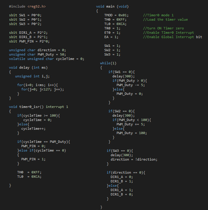
To demonstrate, we use the code above and load it to our microcontroller. Switches connected to P0.0 and P0.1 controls the speed of the motor, switch at P0.2 changes the direction. We user Timer 0 interrupt to generate Pulse Width Modulation (PWM) to control the speed of the motor. By varying the pulse width we change the average value of the voltage going to the motor thus the speed is controlled. To change direction, we follow what was stated in the datasheet.